

Plovdiv
The site – Pilot Area Selection_ – Documentation of the installation – Results
The site
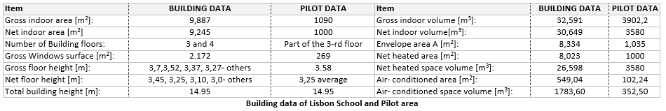
Professional School for Electrotechnics and Electronics (PSEE) is an elite government high school with local significance for the education of young people in the sphere of high education. PSEE has been providing qualified teachers for 40 years. Its professional training is consistent with the requirements of high education standards. Future technicians in electrotechnical Industry, information technology and electronics are prepared in the school. PSEE is a two buildings complex located in West district of Plovdiv, built in 1962 and renovated in 1985. Moreover, the School was refurbished partially, with the change of windows in 2008 (still ongoing action) and the improvement of the heating system in 2012. First buildings has total built area of 1,400 m2, the second one has 1,100 m2. There is a third building bridging the two buildings that has 400 m2 built area. The total built area is 2,900 m2, the total floor area is 8,646 m2, heating volume is 26,388 m2. The PSEE outdoor area is 17,656 m2. During the school year PSEE hosts an average of 939 people. The Pilot area proposed for the VERYSchool project is part of the 3rd floor, with a net indoor area of about 1.600 m2. Pilot consist of classrooms, laboratories, library, corridors and stairs and WC-s. Pilot area hosts approximately 210 people.
Pilot Area Selection
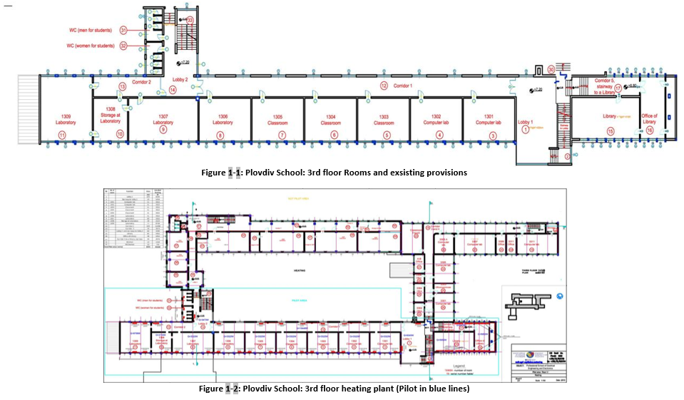
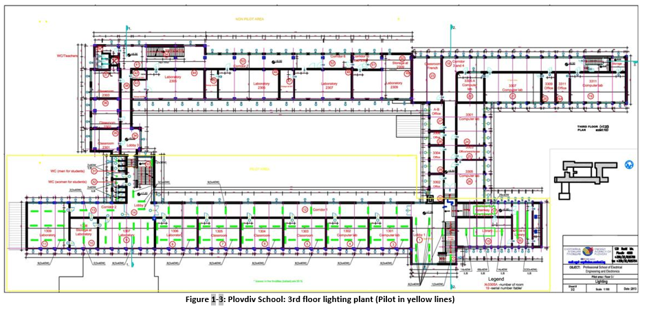
The selected area includess 3 classrooms, 5 laboratories, 1 library, 2 auxiliary offices, 2 lobbies, 3 corridors and 2 bathrooms.
Documentation of the installation
This section describes the documentation prepared for the Pilot with the objective of enabling the installer to perform the specific tasks while minimizing the possibility of errors. Moreover, the whole set of documentation details drawings, layouts, technical specification of equipment to facilitate choices and installing activities. More in detail, the whole set of documentation includes:
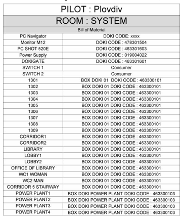
- a list of modules and units to be installed in the Pilot, including the code number of each unit;
- a table which details for every BOX Module of the pilot the pre-setting settled up in the factory, including the DIP switches presets, the IP address, the ID Plovdiv BOX code. In other words every BOX DOKI has been coupled with a IP address (Board IP and WIFI IP) and with the values of DIP Switches 1, 2 and 3 to set up the behavior of the module.
Note: The Box with ID “THERMAL POWER PLANT 4” isn’t installed but left as spare unit for future replacement in case of fault of one of the installed ones.
- a general drawing which summarizes the links between the various modules of the DOKI Bems control network, with specific details of the type of cable to use for all connections (see next session).
- a wiring diagram for each EVO Module (both for control of rooms/premise and for the smart meters) that shows the connections to be performed and the type of cable to be used for each input or output.
- a list of modules and units to be installed in the Pilot, including the code number of each unit;
- a general drawing which summarizes the links between the various modules that constitutes the Pilot with specific details of the type of cable to use for all connections (see figure in the next section);
- a wiring diagram for each EVO Module (both for control of rooms/premise and for measure of energy) that shows the connections to be performed and the type of cable to be used for each input or output (see figures below).