Use Cases
Each use case describes one particular scenario in which the user interacts with the system. A use case is described with a summary and the flow of events. Any precautions taken to respond to mistakes by either the system or the user which do not resemble the base flow of events will be described as well. Each use case has a unique ID and name. Each use case matches exactly one process model.
Use cases and process models were developed in parallel: Input gathered from process models was implemented in the use cases and vice versa. Either presents the full complexity of the scenario across all pilot sites implementing this particular scenario. Hence, certain sites might not cover all steps or implement the flow slightly differently.
Note
Your system does not have to implement the entire complexity to deploy a certain feature. Some steps cover specialised elements and can be “cut out” or come with an “upgrade” later.
The Guide offers a comprehensive list of 49 Use Cases (with Process Models and Requirements) collected from 28 pilot sites traceable by an ID.
Categories / User Groups
In order to reduce the complexity of the use cases and simplify the notation (paths) of each use case, the following assumption is made for user profiles.
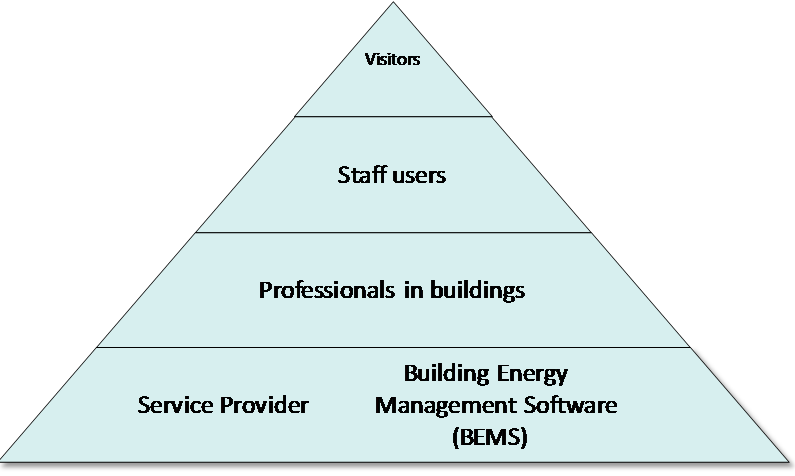
The right and their access to the system of all core target groups can be described as a pyramid. The higher the user is located on the pyramid, the smaller the number of uses cases applicable for this user. Vice-versa, the lower a user is on the pyramid the greater the access to the system.
It is assumed that users further down on the pyramid also have access to all use cases available to any user higher in the pyramid. Hence, though professionals are not listed in the paths of a use case for visitors, the professional is yet able to perform the very same use case with the system. The following figure depicts the pyramid:
Exceptions to the rule
The assumption for the user profile pyramid works well in the majority of process models and for all pilot sites. However, in certain applications of some processes single pilot sites do not follow the rule. This is either due to a technologically very advanced approach or pragmatic solutions to a problem.
Hint
Hence, any replication might slightly adjust the allocation of a use case but keep the grouping to reduce the number you will also need to test.
Technical Overview
Use Cases
Principles
Use cases for SMARTSPACES have to cover the necessities of eleven pilot sites covering very differing approaches and systems. In order to simplify the structure for the reader and to simplify the traceability of requirements among the many different approaches the following principles will be applied to use cases:
- Use cases are actor-centric
- An actor is the starting point of any use case and his first action determines the flow of the use case.
- All use cases are grouped by the actor type;
The main logical use case group (parent) describes several other use cases:
- Parent use cases are limited to the following elements:
- defining a common goal to be achieved by extending use cases;
- describing which use cases extend the parent;
- collecting shared requirements of child use cases.
Grouping of use cases shall not be interpreted as a hierarchy in itself. They are used to limit the complexity of diagrams and avoid repetitions. Furthermore, they simplify the traceability of requirements.
Description of Fields
Use Case ID: Each use case has an individual ID that always starts with “UC” (for use case) and containing separated by underscores i) the user profile (e.g. V for visitor) and ii) an acronym for the particular use case (e.g. LOG for Log-in). A complete example for a use case ID looks like “UC_V_LOG”. If the use case is part of a group (child use case), it’s parent’s ID is extended by the acronym for the particular use case (e.g. UC_V_AWA_RES which describes the use case Resource Awareness as part of the parent case Awareness)
Use Case Name: Each use case should have a unique name suggesting its purpose. The name should express what happens when the use case is performed. Usually a combination of a verb and a noun is chosen which is occasionally extended by adjectives or adverbs (e.g. Login Portal). As for Use Case IDs the name of use cases is the same as for the corresponding process model.
Actor: This field contains the relevant and active actors (user groups). The actor is addressed as ‘the user’ in the use case documentation. ‘The user’ can be male or female. The system is used for the service and Bems in some specialised cases the Building Energy Management System. If not indicated otherwise, “he/him/his” refers to the user.
Summary: The summary gives an overview over the purpose of the use case and provides the ideal outcome (result) of the use case.
Base flow: The base flow describes the steps that the actors and the system go through to accomplish the goal of the use case. The actor takes the first step and then the system responds. It is necessary to ensure that any base flow description covers all potential solutions given that the use case applies for the particular site. Hence, each use case in this deliverable is the common denominator of all pilot sites and contains as much detail as applicable. On site level, each use case can be extended with more steps or detail. Exception paths describe uncommon processing occurring when a given error happens. For instance, the user does not remember his/her password and is redirected to another page.
Triggers: Triggers describe the entry criteria for the use case. This becomes especially important in semi-automatic or automatic processes which apply to ems services. In many cases triggers become obsolete as grouping (parent) use cases describes the entry criteria or motivation for the extending use cases.
Standards used
This documentation has been made following the indications of different norms related on definition of the SOAS (Software as a Service) for team and enterprises such as EEE 1471-2000™ Conceptual Framework for Architectural Description and ISO/IEC/IEEE 42010 System and software – Architecture description.
Process Models
Introduction
The primary goal of BPMN is to provide a notation that is readily understandable by all business users, from the business analysts that create the initial drafts of the processes, to the technical developers responsible for implementing the technology that will perform those processes, and finally, to the business people who will manage and monitor these processes. Thus, BPMN creates a standardised bridge for the gap between the business process design and process implementation.
The process models that are created for SMARTSPACES are based on the use of BPMN 2.0 – the newest version that was released in January 2009.
The main advantages of BPMN are: * Neutral notation, adopted by many solution providers * Growing number of tools available * Diversified usage – from process visualisation to process automation * Simple but powerful semantic
Note
Connection to Use Cases: IDs for process model and use cases share the same syntax and names. The use case UC_V_LOG is described in full detail in the corresponding process model PM_V_LOG.
Principles
The process models have to cover the necessities of 28 pilot sites using very different approaches and systems. In order to simplify the structure for the reader and to simplify the traceability of requirements among the many different approaches the following principles will be applied to process models:
Chronological approach – the process models are oriented on a time line (from left to right);
All tasks or activities are assigned to one of the actor types;
Complex tasks/processes can be modelled in a hierarchical fashion (e.g., with Sub-Processes);
The notation can make use of colours to suit the purpose of the modeller or tool;
The BPMN elements can be of any size to suit the purpose of the modeller or tool;
- “Simplicity in modelling” approach:
- New modelling elements are introduced only if there’s no possible way of modelling a process with the basic elements.
- If there are different ways of modelling a task or method, the most simple is chosen to minimise the size of the process.
The motivation for simplicity lies in considering that different standards of business modelling are being used in all participating and/or potential exploitation sites. Moreover, by reducing the necessity for training unnecessary barriers between IT-experts and involved or deciding personnel in municipalities (or social housing companies etc.) can be avoided and the chances of dialogue between both parties are higher.
Description of Fields
For a description of fields, download the official documentation or search for a (condensed) cheat sheet / chart on the web.
Standards used
The process models follow the BPMN 2.0 open specification maintained by the Object Management Group (OMG). It is based on previous notations such as EPC, UML activity diagrams and Petri Nets.